

A few months ago I went to an interesting garage sale in neighboring Springfield. Held literally in a garage, which was the workshop and storage area of a recently passed-away tube amp and speaker enthusiast, the sale was for the benefit of his widow, and the sheer number of older vintage pieces was astounding. I left with a few purchases, which did not include the old tube amplifier pictured above. About a week later a friend, who was also at the sale, called and said he'd picked up two Stromberg-Carlson ASR-120 stereo amps that day, and had the idea of having a co-op tube amp re-build / re-store / re-imagine project. Cool! Count me in, sounds like fun. As long as we're going through a worldwide epidemic disaster, we might as well have some fun while self isolating.
Here's a schematic of the Stromberg-Carlson ASR-120:

Three cropped views of the schematic; first, the audio circuit:

The power supply:

And the resistance test chart:

This is a very straightforward circuit, elegant in its simplicity, and like other classic minimalist tube amplifiers such as the 1950s Dynaco designs, it should end up sounding really great when we get it back up and running well. Just as in Dynaco Stereo 70 and the Mark series amps, each channel's input signal first runs through the pentode 1/2 of a dual section pentode+triode 9-pin tube, in this case a 7199. Configured as an input buffer and low-gain current driver stage, the output of the pentode runs straight into the grid of the triode section of the 7199, which is wired up as a cathodyne phase inverter, the cathode and anode (plate) of which connect up to the grids of their respective 7408 output tubes (an industrial version of a 6V6 GT). Basically, this circuit is very much like a lower power Dyna ST-70, with one difference being that the output tubes of the Stromberg are cathode biased, rather than fixed biased, as in the Dynacos.
A couple more notes:
- The ASR-120 is a power amplifier only, with no controls, and no preamplifier stages - the Stromberg-Carlson console stereos had a separate, remote tuner and control section within another chassis.
- The six tubes in the tuner section had enough combined gain to run its output at near line level, as did the powerful ceramic phonograph cartridges used in the late 1950s and '60s - no preamp was needed.
- The amplifier's power transformer has a separate 6.3VAC heater tap, as well as an additional secondary voltage tap; those, along with one leg of the AC wall voltage, were routed through a 7 pin connector and then to the tuner+control section - a rectifier circuit provided DC voltage for the plates and screen grids of the tuner's tubes, the additional heater tap went to the filaments of those tubes, and the AC line was hooked up to an on/off switch on the control panel.
Here's a link for a full size download of the ASR-120 schematic, courtesy of Audiophool's Made In Rochester site: http://www.audiophool.com/Schem_A/S-C_ASR-120_schem.gif
One of the Stromberg-Carlson console stereos that the ASR-120 amplifiers were used in, an RP-781 "Young American" model:

Obviously designed in the late '50s, back when even common everyday appliances, such as toasters and TVs, had style.
Okay, getting back to the project in hand, both of the ASR-120 chassis we ended up with had been modified by their previous owner, both slightly differently, but judging by the solder work, both done by the same person. Here's another shot of the amp chassis, showing some of the mods done to it:

Two pairs of 3-way binding posts have been added, one on each side of the chassis, connected to the speaker output transformers' secondaries. Ideally, I would have preferred they were both on the same side, to minimize cable clutter, but oh well, the holes have already been drilled, so they'll stay. Originally, the output transformer secondary wires simply hung loose, and ran to the speakers; whoever did this mod routed the secondaries back inside the amp chassis and then soldered them to the back terminals of the binding posts.
Also, RCA type input jacks have been installed in the top corners of the chassis, where there were already holes - one of those holes originally had wires running from the 6.3V filament circuit to a power-on indicator bulb, and the other is a mystery. In the photo above, you can see a smallish brown circular phenolic plug-in thingie - that was the original audio input port from the tuner/control section. Soon, those two added RCA jacks will be removed, and moved together to one of the amp sides; I don't much like the idea of input cables hanging in mid-air. One idea we're considering is to replace the original input jack whatchamacallit thing, with a dual-section 500K audio taper potentiometer wired as an input attenuator, acting as a volume control.
Interestingly, the spell-check in Blogger passed "whatchamacallit", but rejected "potentiometer" and "attenuator".
More photos. Here's a shot of the multi-section capacitor can, zeroing in on the manufacturing date code - this cap can was made in the 39th week of 1961:

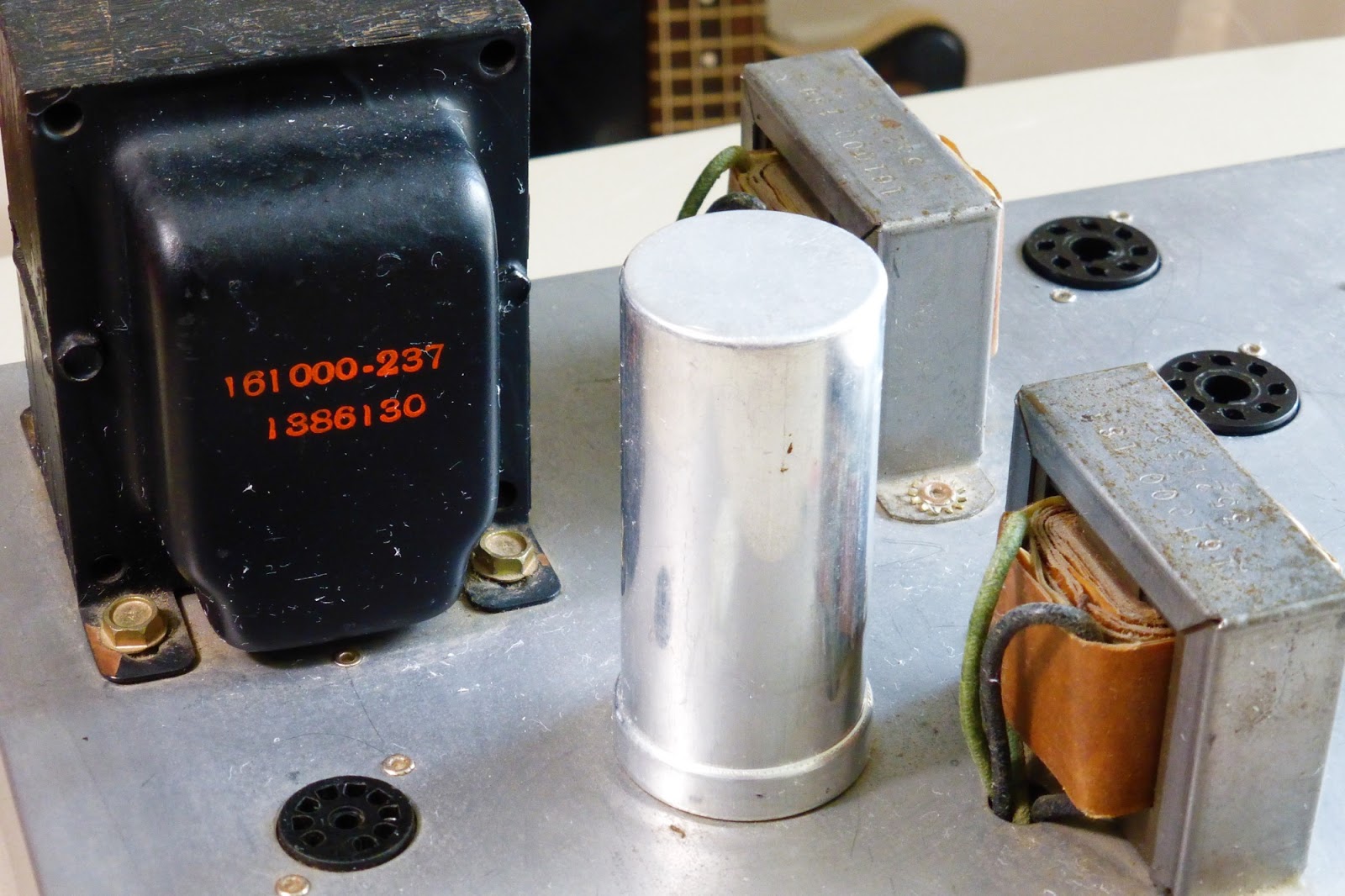
In this next pic, note the power transformer date code, the 30th week of '61. Hey, I'm beginning to think this amp was made in 1961! Just a wild guess:
One last picture of a manufacturer's date code, stamped onto an output transformer:

Another view of the outside of the chassis, before we dive into the innards. Note the white nylon 7-pin connector that used to carry the three voltages (described a few paragraphs ago) between the amplifier chassis and the tuner + control section. It's doubtful that this amp will ever go back to the glamorous life it enjoyed in the 1960s; that connector, and its associated wiring, will probably be removed:

Next, a photo of the ASR-120's circuitry. In the following two pictures we'll talk about some of what we see here, both what's original and what's been previously modified. In this shot you can see the four rubber feet that were probably added by a former owner, to enable the amp's use as a stand-alone unit; originally, the amplifier was attached firmly to the console cabinet with wood screws:

This next photo shows the power supply wiring: AC line in, power transformer leads, rectifier tube socket terminals, multi-section capacitor can terminals, and associated wiring and other components. Also note the wiring from the terminal strip to the multi-connector, which originally sent supply voltages to the tuner/control unit. The fuse holder, which appears to be glued onto the chassis, has been added within the past 59 years; the original fuse was a pigtail type, soldered directly onto the terminal strip:

One last picture. We're looking at the terminal sides of six tube sockets, the original audio input connector (between the two 7199 tube sockets), and the novel use of a perf board as a tag strip for most of the resistors and capacitors in the circuit. As for what's been added as mods, note the speaker output binding posts, the RCA type audio input jacks, two .1uF DC-blocking caps inline with those input jacks, and two 470K resistors soldered onto the terminals of the original input connector. These 470K resistors, the same value as used in a Dynaco Stereo 70, were added by the previous owner to set the input impedance of the 7199 tubes' pentode sections; originally, the volume control in a Strombarg-Carlson console stereo's tuner/control panel determined that, as well being an input signal attenuator:

Eventually, we're going to do some fun stuff, such as rewiring the 7199 tube sockets to accept other, more readily available (as well as cheaper!) pentode+triode 9-pin tubes, and ripping out some wires and tossing them. After that, we'll pop in some tubes, hook up a couple speakers, and test this little beast.
But first, in Part 2, we'll take a look at the Stromberg-Carlson ASR-120 rebuild done by David from Massachusetts, very nice indeed.
Also, please feel free to get in touch. Being merely a hobbyist, holding no advanced degree in Vintage Tube Ampology, I've no doubt made some dumb assumptions about the circuitry of this amp. Having said that, I'm always willing to learn new stuff, and invite your comments and corrections.
In the meantime, stay safe, stay healthy, and don't hoard toilet paper!
12 comments:
I just got a 120, so I'm watching your build intently.
Hi Nirky -
Thanks for checking out the blog! If you go to the end of the Stromberg Amp Part 1 post, there's a link to Part 2, which shows a restoration rebuild done by a friend on another ASR-120. Really nice work, and very informative: https://origaminightlamp.blogspot.com/2020/05/stromberg-carlson-asr-120-stereo-tube.html
As for the chassis shown in this post, I'm finally getting around to working on it; the next post is going to be on converting the 7199 sockets for use with 6GH8 and 6U8 pentode+triode tubes.
Cheers!
---Jim
I am also working on this exact same power amp, my first attempt at working with electronics. Both part 1 and 2 have been super helpful! I look forward to part 3.
Thanks!
Hi -
Thanks for checking out the blog posts on the S-C ASR-120! Due to having too many other projects the third installment on my own ASR has been delayed, but expect Part 3 within a week or so. Also best of luck with your 1st audio project.
---Jim
Thanks! I am really interested to see how you install the new power caps.
-CM
Hi Cm -
Woops, got busy with some home repairs (not very bloggable), and so behind schedule on the ASR amp again.
As for the filter capacitors, they test out okay w/ meter, within spec tolerance - so won't think about replacement until the amp is up and running and audio torture tested. Although many assume old caps to always be near death, in my experience that's not always true. I have 50 year old tube amps with original filters that run smooth and silent - see my post on the RCA RS-193.
If the filters need replacement, the plan is to disconnect the big shiny cap can, leave it in for looks, then install another terminal strip and put new individual compact capacitors on it and wire them into the circuit. See Part 2 for an example of how my friend did something similar.
---Jim
Unfortunately the power cap can on mine was not running smooth. It was easy to get off, carefully open up, and remove the guts from it. I have seen where some folks take the time to put new caps inside and reinstall. I am still looking at options.
What about the rivets that hold the OTs and tube sockets to the chassis? If you remove those will you put them back with the same sort of rivet, or go to nuts and bolts?
Thanks again!
-CM
This is probably one of the better console amps. The only problem for modern DIYers is the 7199 driver tube, as you point out. If you need help with the replacements, Eli Duttman at Tube DIY Asylum has it nailed. I bought one of these amps inexpensively on the 'Bay about six years ago. It sat for several years, and being as I don't need more fodder for hi-fi use, the chassis eventually became a prototype guitar amp. The rectifier tube was replaced with solid state, and the two output transformers were removed in favor of an OPT from a Peavey Classic 30. I changed the output stage to a pair of EL34 and added a bias supply to eliminate the voltage drop inherent to self bias. With the Stromberg power transformer, this arrangement provides about +400V on the tubes and produces a good, solid 30W RMS output on the bench.
Your amp should do a very credible job in stereo with a few mods and the right speakers. Good luck with the project!
Anonymous-
Thanks for the comment. That sounds like a great and original sounding re-purposing of one of these amps! If you have any photos, I'd be very interested in seeing how the project looks. I've recycled an old organ amp and rewired it as a '50s Pro circuit for use w/ a Leslie cab, but haven't (yet) done similar with a console stereo amp. What sort of preamp are you using for guitar use?
And yeah, eventually this ASR-120 will be my main home audio amp, probably more suited to the space than the overkill pair of Dynaco Mk III.
CM-
You kinda lost me at "carefully open up, and remove the guts..."
I'm pretty sure that those "guts" are carcinogenic, just saying. Replacement multi-section capacitor cans are relatively inexpensive, especially the JJ brand (which does require a separate clamp, but that's cheap too). Even cheaper is mounting individual filter caps inside the chassis.
If you want to replace the tube sockets (a big job including all the rewiring), small bolts, nuts, and star washers are the right way to mount new sockets. Are the sockets fried? If not, possibly no reason to replace them. First, get the filter caps back up and running, pop the tubes in, and test the amp before getting too far into it. The old "one thing at a time" method is usually best, although sometimes it's fun to replace everything.
Been 6 months. This project is on the back burner?
Hi Nirky -
I admit it, I have way too many projects going, on every burner of the stove, more than I can possibly eat at one time. Funny thing is, all the necessary parts are already on hand ready to go, but other fun things get in the way. Some day, maybe even this year!
Post a Comment